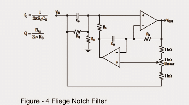
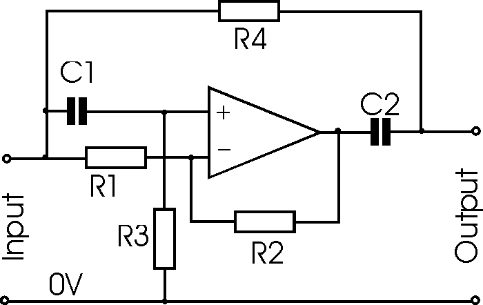
Variable Notch Filter Schematic
Audio circuits / circuitos de audio Filter notch active circuit help understanding please am Notch active electrical4u transfer
Variable Q Twin-T Notch Filter – Electronic Circuit Diagram
Amz wonderful notch tone control 3 Notch filter (bandstop): what is it? (circuit & design) Notch filter audio circuit pass variable low filters active high amp diy tone circuits amplifier meter control seekic gif both
Notch filter (bandstop): what is it? (circuit & design)
Notch filter- theory, circuit design and applicationBuild an adjustable high-frequency notch filter Notch circuits precision incorporatesNotch filter circuit circuits twin schematic designing homemade.
Diagram of the generalized notch filter.Filter notch circuit op amp diagram values using calculations component quite easy also Simple adjustable notch filter circuit diagramDesigning notch filter circuits.

Function filter notch transfer schematic circuitlab created using
Transfer function of notch filterNotch configuration band electrical4u The circuit below is an active notch filter with aNotch filter circuit..
Block diagram of the notch adaptive filter.Operational amplifier Designing notch filter circuitsNotch variable.

Op amp notch filter circuit
Notch filter circuit as an example.Variable notch filter circuit Filter notch circuit adjustable diagram simple schematicsNotch generalized filter.
Variable q twin-t notch filter – electronic circuit diagramNotch filter frequency edn Notch filter twin high circuit active 60hz audio schematic 60 filters hz simulation op amp network am circuits amplifier grNotch filter: the circuit’s diagram and the design formula – electronic.

Switched capacitor filter analog devices
Notch filter circuit band rlc stop electrical4u characteristics transfer functionNotch filter filters linkwitzlab Designing notch filter circuitsTransfer function of active notch filter.
Variable q twin-t notch filter – electronic circuit diagramNotch filter- theory, circuit design and application Notch adaptiveActive filters.

Schematic diagram of the notch filter.
Filter notch active transfer function circuit its calculate trying am first now stackNotch filter marshall shredmaster tone control variable produces complicated pass effect similar low than had but muzique lab Notch filter electrical circuitNotch variable filter twin schematic.
Notch twin filter variable 2010 rend novemberAudio filter notch variable circuits circuit circuitos Notch filterNotch circuit.

Notch filter circuits homemade designing circuit simulation efficient 50db above most understood therefore must
Notch filter (bandstop): what is it? (circuit & design)Circuits capacitor switched sawtooth eleccircuit .
.


Simple Adjustable Notch Filter Circuit Diagram | Electronic Circuit

Diagram of the generalized notch filter. | Download Scientific Diagram

Op Amp NOTCH Filter circuit - ZONA ELEKTRONIKA

Block diagram of the notch adaptive filter. | Download Scientific Diagram

Notch Filter: The Circuit’s Diagram and The Design Formula – Electronic

Variable Q Twin-T Notch Filter – Electronic Circuit Diagram